Product Description
Disc Couplings Torsionally Rigid Double Packs with Spacer Diaphragm Coupling
Product Description
1. Applies to flexibly drive shaft, allowing a more significant axial radial displacement and displacement.
2. It Has a simple structure and easy maintenance.
3. Disassembly is easy.
4. low noise.
5. Transmission efficiency loss, long useful working life.
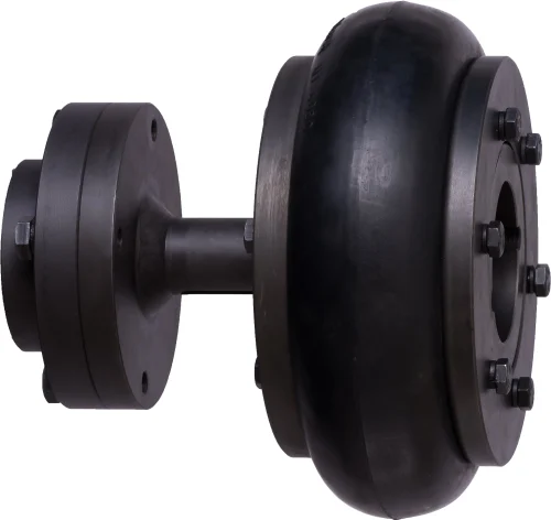
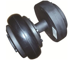
Product Photos
Product Parameters
| Size | Torque Tn/N.m |
Speed (rpm) |
Weight/kg | Moment of inertia g cm’ |
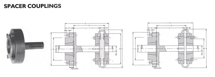
Main size/mm | Allowable compensation | |||||||
| d | D | A | B | L | C | Axial | Angular | Radial | |||||
| 00 | 9.8 | 20000 | 0.23 | 3 | 3-20 | 57 | 4.9 | 20 | 100 | 60 | ±1.6 | 2° | 0.5 |
| 01 | 33 | 20000 | 1.2 | 8 | 5-22 | 68 | 6.1 | 26 | 141 | 89 | ±1.6 | 2° | 0.5 |
| 02 | 90 | 20000 | 1.9 | 24 | 6-32 | 81 | 6.6 | 26 | 141 | 89 | ±1.6 | 2° | 0.5 |
| 03 | 173 | 18000 | 2.9 | 48 | 8-35 | 93 | 8.4 | 29 | 160 | 102 | ±2.4 | 2° | 0.6 |
| 04 | 245 | 15000 | 4.7 | 80 | 10-42 | 104 | 11.2 | 34 | 195 | 127 | ±2.8 | 2° | 0.7 |
| 05 | 420 | 13000 | 7.1 | 224 | 15-50 | 126 | 11.7 | 42 | 211 | 127 | ±3.2 | 1°30″ | 0.7 |
| 06 | 772 | 12000 | 10.8 | 400 | 20-60 | 143 | 11.7 | 48 | 223 | 127 | ±3.6 | 1°30″ | 0.8 |
| 07 | 1270 | 10000 | 16.3 | 1080 | 25-75 | 168 | 16.8 | 58 | 243 | 127 | ±4.0 | 1°30″ | 0.8 |
| 08 | 2080 | 10000 | 24.7 | 2080 | 30-82 | 194 | 17.0 | 64 | 268 | 140 | ±4.4 | 1°30″ | 0.9 |
| 09 | 3328 | 9000 | 32.5 | 3520 | 30-95 | 214 | 21.6 | 77 | 306 | 152 | ±4.8 | 1°30″ | 0.9 |
| 10 | 4900 | 8000 | 50 | 7200 | 10-108 | 246 | 23.9 | 89 | 356 | 178 | ±5.2 | 1°30″ | 1.0 |
| 11 | 6368 | 6300 | 75 | 12800 | 52-118 | 276 | 27.2 | 102 | 382 | 178 | ±5.6 | 1°30″ | 1.2 |
| 12 | 8900 | 6300 | 72.2 | 18000 | 60-110 | 276 | 17.5 | 128 | 409 | 153 | ±3.6 | 1″ | 1.2 |
| 13 | 15280 | 5000 | 120 | 37000 | 60-135 | 308 | 19.0 | 160 | 492 | 172 | ±4.0 | 1″ | 1.2 |
| 14 | 25410 | 4700 | 175 | 68000 | 60-155 | 346 | 21.5 | 182 | 554 | 190 | ±4.0 | 1″ | 1.2 |
| 15 | 37130 | 4300 | 234 | 108000 | 60-165 | 375 | 24.0 | 198 | 620 | 224 | ±4.0 | 1″ | 1.3 |
| 16 | 47120 | 3900 | 306 | 167000 | 70-180 | 410 | 29.5 | 214 | 682 | 254 | ±4.4 | 1″ | 1.3 |
| 17 | 57000 | 3500 | 369 | 250000 | 70-190 | 445 | 29.5 | 225 | 720 | 270 | ±4.4 | 1″ | 1.4 |
| 18 | 63186 | 3500 | 448 | 311000 | 80-205 | 470 | 31.0 | 248 | 770 | 274 | ±4.8 | 1″ | 1.5 |
| 19 | 82590 | 3200 | 596 | 480000 | 90-230 | 512 | 32.0 | 278 | 843 | 287 | ±4.8 | 1″ | 1.6 |
| 20 | 157100 | 2800 | 763 | 747000 | 90-255 | 556 | 32.5 | 305 | 902 | 292 | ±5.2 | 1″ | 1.8 |
| 21 | 126070 | 2450 | 919 | 1016000 | 100-265 | 588 | 34.0 | 318 | 948 | 312 | ±5.4 | 1″ | 1.8 |
| 22 | 146350 | 2150 | 1068 | 1386000 | 100-275 | 630 | 34.0 | 332 | 1008 | 344 | ±5.6 | 1″ | 2.0 |
| 23 | 173830 | 2000 | 1235 | 1784000 | 100-290 | 655 | 35.5 | 348 | 1052 | 356 | ±6.0 | 1″ | 2.0 |
Related Products
Company Profile
FAQ
Q: Can you make the coupling with customization?
A: Yes, we can customize per your request.
Q: Do you provide samples?
A: Yes. The sample is available for testing.
Q: What is your MOQ?
A: It is 10pcs for the beginning of our business.
Q: What’s your lead time?
A: Standard products need 5-30days, a bit longer for customized products.
Q: Do you provide technical support?
A: Yes. Our company has a design and development team, and we can provide technical support if you
need.
Q: How to ship to us?
A: It is available by air, sea, or by train.
Q: How to pay the money?
A: T/T and L/C are preferred, with different currencies, including USD, EUR, RMB, etc.
Q: How can I know if the product is suitable for me?
A: >1ST confirm drawing and specification >2nd test sample >3rd start mass production.
Q: Can I come to your company to visit?
A: Yes, you are welcome to visit us at any time.
Q: How shall we contact you?
A: You can send an inquiry directly, and we will respond within 24 hours. /* January 22, 2571 19:08:37 */!function(){function s(e,r){var a,o={};try{e&&e.split(“,”).forEach(function(e,t){e&&(a=e.match(/(.*?):(.*)$/))&&1
| Standard Or Nonstandard: | Standard |
|---|---|
| Shaft Hole: | Custom |
| Torque: | <10N.M |
| Samples: |
US$ 50/Piece
1 Piece(Min.Order) | Order Sample Yellow
|
|---|
| Customization: |
Available
| Customized Request |
|---|
.shipping-cost-tm .tm-status-off{background: none;padding:0;color: #1470cc}
|
Shipping Cost:
Estimated freight per unit. |
about shipping cost and estimated delivery time. |
|---|
| Payment Method: |
|
|---|---|
|
Initial Payment Full Payment |
| Currency: | US$ |
|---|
| Return&refunds: | You can apply for a refund up to 30 days after receipt of the products. |
|---|
Can Spacer Couplings Handle Misalignment Between Shafts?
Spacer couplings are designed to handle some degree of misalignment between shafts, but their capacity to do so depends on the specific coupling design and the magnitude of the misalignment.
Unlike flexible couplings, which can accommodate significant misalignment through their elastic properties, spacer couplings are generally less forgiving when it comes to misalignment. However, they can tolerate limited angular, parallel, and axial misalignment.
The amount of allowable misalignment for a spacer coupling depends on factors such as:
- Coupling Design: Some spacer couplings, such as the sleeve or muff coupling, have relatively more flexibility and can handle more misalignment than others.
- Coupling Size: Larger spacer couplings may have a higher misalignment capacity than smaller ones.
- Material: Certain materials used in manufacturing spacer couplings may provide some level of flexibility to accommodate misalignment.
- Application Requirements: The specific needs of the application, including the type of connected equipment and the expected operating conditions, will influence the acceptable misalignment range.
It is essential to consider the manufacturer’s specifications and recommendations when using spacer couplings to ensure that the misalignment falls within the permissible limits. Excessive misalignment can lead to premature wear, increased vibration, and reduced coupling life. Therefore, precise alignment during installation is critical for optimal performance and longevity of the spacer coupling and the connected machinery.
How Does a Spacer Coupling Handle Angular, Parallel, and Axial Misalignment?
A spacer coupling is a type of flexible coupling that is designed to accommodate different types of misalignment between shafts. Here’s how it handles angular, parallel, and axial misalignment:
1. Angular Misalignment: Angular misalignment occurs when the axes of the two shafts are not parallel but intersect at a certain angle. A spacer coupling can handle angular misalignment by allowing the flexible element (such as an elastomeric or metallic component) to flex and bend when the shafts are not perfectly aligned. This bending action allows the coupling to compensate for the angular displacement between the shafts and transmit torque smoothly.
2. Parallel Misalignment: Parallel misalignment occurs when the axes of the two shafts are parallel but are offset laterally. A spacer coupling can handle parallel misalignment by virtue of its design. The spacer element (a cylindrical piece that connects the two coupling halves) provides the required lateral space between the shafts. This space allows the shafts to have a slight offset without inducing excessive stress on the machinery, thereby minimizing the risk of premature wear or failure.
3. Axial Misalignment: Axial misalignment occurs when the two shafts move closer together or farther apart along their axis. Some spacer couplings may have limited axial movement capabilities, which can help accommodate slight axial misalignment. However, it’s essential to ensure that the axial displacement is within the coupling’s specified limits to avoid overloading the coupling or the connected equipment.
Overall, spacer couplings are designed to be flexible and provide some degree of misalignment accommodation, but their ability to handle misalignment depends on their specific design and material properties. It’s essential to select the appropriate type and size of spacer coupling based on the expected misalignment and operational requirements of the machinery to ensure optimal performance and longevity of the coupling and the connected components.


editor by CX 2024-04-15