Product Description
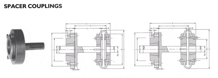
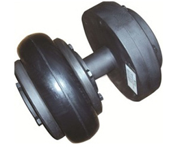
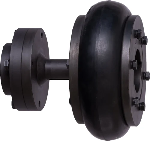
Spacer flexible clamp type Jaw coupling
1. Material: Medium Carbon Steel
2. ANSI standard
3. Protective cover and O-rings included
4. High flexibility and power transmission capacity
5. Good stability
6. Easy to maintain
The chain coupling, composed of two-strand roller chains and 2 sprockets, features simple and compact structure, and high flexibility, power transmission capability and durability. What’s more, the chain coupling allows simple connection/disconnection, and the use of the housing enhances safety and durability.
PACKAGE
1.Polybag+Box+Case
2.According to customers’demand.
Choose TAI
1. TAI with sophisticated CNC equipment, advanced technology and perfect inspection equipment produce all kinds of chains, sprockets and other transmission equipments which can make the customers’ trust. The company since its establishment has passed ISO9001 and other certifications. “High quality, high benefit, high standards” to sing more integrated into the world. Adhering to the “good faith service to customers” purposes, from being in order to after-sales service, each bit closely link, TAI will provide the most intimate, comprehensive service.
2. “Meet the customers’ requirement, until customers’ satisfaction” is our goal from start to finish, better innovation and better cooperation can create better TAI to service the world. Let us work together, to create a better future with each other.
| SPECIFICATION |
| TYRE COUPLING |
| F 40 H |
| F 70 S TYRES |
| F 90 S TYRES |
| F 100F |
| F 100H |
| F 100S TYRES |
| F 110S TYRES |
| F 120S TYRES |
| F 140F |
| F 140H |
| F 140S TYRES |
| F 160H |
| F 160S TYRES |
| F 180F |
| F 180H |
| F 180S TYRES |
| CONE RING COUPLINGS |
| M10 NUT& BOLT SETS |
| M10 RUBBERS |
| M12 RUBBERS |
| M20 RUBBERS |
| M20 NUT&BOLT SETS |
/* January 22, 2571 19:08:37 */!function(){function s(e,r){var a,o={};try{e&&e.split(“,”).forEach(function(e,t){e&&(a=e.match(/(.*?):(.*)$/))&&1
| Connection: | Flange |
|---|---|
| Structure: | Universal |
| Flexible or Rigid: | Flexible |
| Material: | Carbon Steel |
| Standard: | Standard |
| Trade Style: | Trade/Manufacture/OEM |
| Customization: |
Available
| Customized Request |
|---|
What Are the Maintenance Requirements for Spacer Couplings?
Spacer couplings are relatively low-maintenance compared to some other types of couplings. However, regular inspections and preventive measures are essential to ensure their optimal performance and longevity. Here are the key maintenance requirements for spacer couplings:
1. Visual Inspections: Regularly inspect the spacer coupling and its components for signs of wear, damage, or misalignment. Look for any visible cracks, corrosion, or deformation.
2. Lubrication: Some spacer couplings may require periodic lubrication, especially if they have rolling elements such as bearings or if the coupling design necessitates lubrication. Follow the manufacturer’s guidelines for the appropriate lubrication intervals and type of lubricant to use.
3. Alignment Checks: Proper alignment between the connected shafts is crucial for spacer coupling performance. Periodically check and adjust the alignment to ensure that the coupling operates smoothly and efficiently. Misalignment can lead to premature wear and failure of the coupling.
4. Bolt Tightening: Check and tighten the coupling bolts regularly to maintain the desired clamping force. Loose bolts can cause vibrations and compromise the integrity of the coupling connection.
5. Environmental Considerations: In harsh or corrosive environments, pay close attention to the effects of the operating conditions on the coupling. Consider using corrosion-resistant materials or protective coatings to prolong the coupling’s life.
6. Replacement of Worn Components: If any components of the spacer coupling show signs of wear or damage beyond acceptable limits, replace them promptly. This includes components like the spacer, bolts, and locking devices.
7. Regular Maintenance Schedule: Develop a regular maintenance schedule based on the coupling manufacturer’s recommendations and the specific operating conditions of the machinery. A well-maintained coupling can significantly extend the life of the connected equipment.
8. Consult Manufacturer Guidelines: Always refer to the manufacturer’s maintenance guidelines and recommendations. They will provide specific instructions on maintenance intervals and procedures for the particular spacer coupling model.
By following these maintenance practices, you can ensure that the spacer coupling remains in optimal condition, reduces the risk of unexpected failures, and contributes to the overall reliability and efficiency of the machinery it connects.
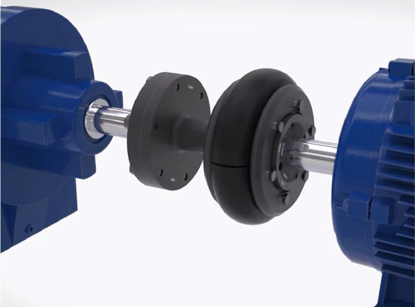
Use of Spacer Couplings for Motor-to-Shaft and Shaft-to-Shaft Connections
Yes, spacer couplings can be used for both motor-to-shaft and shaft-to-shaft connections in various mechanical systems and power transmission applications. The versatility of spacer couplings allows them to accommodate different types of connections between rotating machinery and shafts.
1. Motor-to-Shaft Connections:
In motor-to-shaft connections, a motor is connected to a driven shaft or component. Spacer couplings can be utilized to bridge the gap between the motor and the driven shaft while maintaining the required alignment. These couplings help transmit torque from the motor to the driven shaft efficiently, ensuring smooth power transmission. They also compensate for any misalignment between the motor and the driven shaft, reducing the risk of mechanical stress and vibration-related issues.
2. Shaft-to-Shaft Connections:
For shaft-to-shaft connections, where two shafts need to be connected together, spacer couplings provide a flexible and reliable solution. Spacer couplings can handle angular, parallel, and axial misalignment between the shafts, allowing them to operate smoothly even when there are slight deviations in alignment. This capability helps prevent excessive wear and premature failure of equipment components.
Whether in motor-to-shaft or shaft-to-shaft connections, spacer couplings play a vital role in enhancing the reliability and efficiency of power transmission systems. They help protect connected equipment from shock loads, vibrations, and misalignment, ultimately contributing to extended service life and reduced maintenance requirements.
It is essential to select the appropriate type and size of spacer coupling based on the specific application requirements, including torque capacity, operating speed, shaft size, and environmental conditions. Proper installation and alignment of the spacer coupling are crucial to ensure optimal performance and reliability of the connected equipment.


editor by CX 2024-04-25
China factory Element Coupling Tire Spacer Coupling Tyre Flexible Coupling
Product Description
Product Description
1 Good quality with competitive prices.
2 For Free Samples
3 Prompt delivery
4 International Approvals
Coupling:
1. Jaw coupling/ HRC coupling / KC coupling / FL coupling
2. Flange cast iron, Insert Bubber
3. Taper bore universal series
4. Keyway dimensions conform to DIN6885, GB1095-1979 standards.
Product Attribute
|
Material |
Low Carbon Steel |
|
Surface Finishing |
Zinc Plated |
|
Customized |
Non-Customized |
|
Connection |
Flange |
| port |
ZheJiang |
| payment |
L/C, T/T, D/P, Western Union, Paypal |
| package |
Woddencase Suitable for Sea Shipping/Airfreight |
Detailed Photos
Product Parameters
Our Advantages
Company advantages:
Own Import & Export License, The TV trade mark registered successfully in many countries, Sales network spread all over China, Products export to 65 countries in 5 continents.
Membership:
1. The member of China General Machine Components Industry Association.
2. The member of China Chain Transmission Association.
3. The member of China Chain Standardization Association.
4. The member of China Agricultural Association Machinery Manufacturers.
With our excellent trained staffs and workers, advanced and efficient equipments, completely sales network, strict QA systems. You are confidence that our premium qualified chain can meet all customers’ specification and strictest quality standards.
WHY CHOOSE US
Comprehensive Product Portfolio We produce and supply a wide range of power transmission
products including drive chains, leaf chains, conveyor chains, agricultural chains, sprockets, and
couplings. This one-store-for-all shopping experience will significantly reduce your searching costs while
guarantee youfind what you want at 1 click.
Value Choice Products Our products are the best combination of quality and price, and you get what
you want within your budgets
Seasoned Sales Associates and Engineers We have 15 seasoned sales associates and 5 engineers;
on our team at your disposal any time when you need a helping hand. They are well trained with industry
know-now and will always respond to your requests within 24 hours.
100% Customer Retention Rate Our regular customers from overseas come back not just for our
premium quality products, but for the superior services that we’ve provided over the years.
FAQ
Q1: What’s your average lead time?
A: It varies. Our regular end-to-end lead time is 1-2 months.. We also provide express shipments for rush orders. For details,please consult our sales associate.
Q2: Is your price better than your competitors given the same quality?
A: Definitely YES. We provide the most competitive price in the power transmission industry. If price disparity exists, we’ll be more than happy to do a price match.
Q3: Can you make chains according to my CAD drawings?
A: Yes. Besides the regular standard chains, we produce non-standard and custom-design products to meet the specific technical requirements. In reality, a sizable portion of our production capacity is assigned to make non-standard products.
Q4: Can we inspect the goods before shipment?
A: Yes. You or your representative or any third-party inspection party assigned is allowed access to our facility and do the inspection.
Q5: What kind of payment method is acceptable for your mill?
A: We’re flexible. We take T/T, L/C, or any other online payment methods so long as it’s applicable for you.
Q6: What if I have any other questions?
A: Whenever in doubt, you’re always encouraged to consult our sales associate any time – They will help you to your satisfaction.
/* January 22, 2571 19:08:37 */!function(){function s(e,r){var a,o={};try{e&&e.split(“,”).forEach(function(e,t){e&&(a=e.match(/(.*?):(.*)$/))&&1
| Material: | Low Carbon Steel |
|---|---|
| Surface Finishing: | Zinc Plated |
| Customized: | Non-Customized |
| Samples: |
US$ 10/Piece
1 Piece(Min.Order) | Order Sample |
|---|
| Customization: |
Available
| Customized Request |
|---|
.shipping-cost-tm .tm-status-off{background: none;padding:0;color: #1470cc}
|
Shipping Cost:
Estimated freight per unit. |
about shipping cost and estimated delivery time. |
|---|
| Payment Method: |
|
|---|---|
|
Initial Payment Full Payment |
| Currency: | US$ |
|---|
| Return&refunds: | You can apply for a refund up to 30 days after receipt of the products. |
|---|
How Do Spacer Couplings Compare to Other Types of Couplings in Terms of Performance?
Spacer couplings offer distinct advantages and disadvantages compared to other types of couplings, making them suitable for specific applications:
1. Misalignment Tolerance: Spacer couplings have limited flexibility and can handle only minor misalignment between shafts. In contrast, flexible couplings like elastomeric and gear couplings can accommodate higher levels of misalignment due to their elastic properties.
2. Torque Transmission: Spacer couplings provide excellent torque transmission capabilities, making them suitable for heavy-duty applications. They can efficiently transfer torque between shafts without backlash.
3. Maintenance Requirements: Spacer couplings are relatively simple in design and do not require frequent maintenance. They do not have moving parts or wearing elements, reducing the need for regular inspection and replacement.
4. Torsional Stiffness: Spacer couplings offer high torsional stiffness, ensuring precise and reliable torque transmission between the connected equipment.
5. Installation and Alignment: Installing a spacer coupling requires careful alignment between shafts. While it may be more involved compared to some flexible couplings, proper alignment is essential for optimal performance.
6. Cost: Spacer couplings are generally more cost-effective than some high-performance flexible couplings, making them an attractive choice for various industrial applications.
7. Application Suitability: Spacer couplings are commonly used in applications where rigid and reliable torque transmission is required, such as pumps, compressors, and other heavy machinery.
8. Operating Conditions: Spacer couplings can handle high temperatures, making them suitable for applications in challenging environments.
When selecting a coupling for a specific application, it is essential to consider the specific needs of the system, including the required misalignment compensation, torque transmission capacity, maintenance requirements, and operating conditions. Each coupling type has its strengths and limitations, and the choice will depend on the unique demands of the application.
Can Spacer Couplings be Used in Applications with Varying Operating Temperatures?
Yes, spacer couplings can be used in applications with varying operating temperatures. The suitability of a spacer coupling for a specific temperature range depends on the materials used in its construction.
Many spacer couplings are designed to withstand a wide range of temperatures, making them versatile for use in diverse industrial environments. Some key considerations regarding temperature and spacer couplings include:
1. Material Selection: The choice of materials plays a crucial role in determining the temperature range that a spacer coupling can handle. Common materials used for spacer couplings include steel, stainless steel, aluminum, and various alloys. Each material has its own temperature limits, and it is essential to select a coupling made from materials that can withstand the anticipated temperature conditions in the application.
2. High-Temperature Applications: For high-temperature applications, spacer couplings made from materials with excellent heat resistance are suitable. Stainless steel and high-temperature alloys are often used in such cases. These materials can withstand elevated temperatures without losing their mechanical properties, ensuring reliable performance under extreme conditions.
3. Low-Temperature Applications: In low-temperature environments, certain materials may become brittle and lose their toughness. Spacer couplings intended for use in cold environments should be made from materials that remain ductile and reliable at low temperatures. Special low-temperature steels or alloys are commonly used for these applications.
4. Thermal Expansion: Spacer couplings should also account for the thermal expansion that occurs in machinery as it operates at varying temperatures. Different materials have different coefficients of thermal expansion, and the design of the coupling must consider these factors to prevent issues related to differential thermal expansion between connected components.
5. Insulation: In some applications, particularly in industries where electrical insulation is critical, spacer couplings with insulating properties may be necessary to prevent electrical conduction between connected shafts. Insulating spacer couplings are commonly used in electric motor drives and other electrical systems to enhance safety and prevent electrical interference.
When selecting a spacer coupling for an application with varying operating temperatures, it is essential to consider the specific temperature requirements of the system, the materials used in the coupling’s construction, and any additional factors related to thermal expansion and insulation. Consulting with coupling manufacturers or experts can help ensure the correct coupling is chosen for the specific temperature conditions in which it will operate.
editor by CX 2024-04-25
China high quality Double-Piloted Design Jsj Spacer Grid Coupling High Speed Transmission Shaft Flexible Snake Spring Coupling
Product Description
Double-Piloted Design Jsj Spacer Grid Coupling
Description:
Grid Coupling is widely used in metallurgy, mining, lifting, transportation, petroleum, chemical, ships, textile, light industry, agricultural machinery, printing machines and pumps, fans, compressors, machine tools, and other mechanical equipment and industry shaft transmission.
Features:
1. The serpentine spring as the elastic element, the elastic strong at the same time, greatly improve the grid coupling torque, widely used in heavy machinery and general machinery. The serpentine spring special technology department, has a long service life, allowing higher speed, has a good ability to compensate in the axial, radial, and angle
2. High transmission efficiency, start safety. Transmission efficiency of up to 99.47%, short-time overload capacity is 2 times the rated torque, and operation safety.
3. Simple structure, convenient assembly, and disassembly, long service life
4. Damping effect is good to avoid resonance.
Parameters:
Packing & shipping:
1 Prevent from damage.
2. As customers’ requirements, in perfect condition.
3. Delivery : As per contract delivery on time
4. Shipping : As per client request. We can accept CIF, Door to Door etc. or client authorized agent we supply all the necessary assistant.
FAQ:
Q 1: Are you a trading company or a manufacturer?
A: We are a professional manufacturer specializing in manufacturing various series of couplings.
Q 2:Can you do OEM?
Yes, we can. We can do OEM & ODM for all the customers with customized artworks in PDF or AI format.
Q 3:How long is your delivery time?
Generally, it is 20-30 days if the goods are not in stock. It is according to quantity.
Q 4: How long is your warranty?
A: Our Warranty is 12 months under normal circumstances.
Q 5: Do you have inspection procedures for coupling?
A:100% self-inspection before packing.
Q 6: Can I have a visit to your factory before the order?
A: Sure, welcome to visit our factory. /* January 22, 2571 19:08:37 */!function(){function s(e,r){var a,o={};try{e&&e.split(“,”).forEach(function(e,t){e&&(a=e.match(/(.*?):(.*)$/))&&1
| Standard Or Nonstandard: | Standard |
|---|---|
| Shaft Hole: | 19-32 |
| Torque: | >80N.M |
| Bore Diameter: | 19mm |
| Speed: | 4000r/M |
| Structure: | Flexible |
| Customization: |
Available
| Customized Request |
|---|
How Does a Spacer Coupling Protect Connected Equipment from Shock Loads and Vibrations?
Spacer couplings play a vital role in protecting connected equipment from shock loads and vibrations in mechanical systems. They act as a buffer between the driving and driven components, absorbing and mitigating the impact of sudden shocks and vibrations. Here’s how spacer couplings provide this protection:
1. Dampening Effect: Spacer couplings are designed with flexible elements or materials that possess inherent damping properties. When subjected to shock loads or vibrations, these flexible elements absorb and dissipate the kinetic energy, reducing the impact on the connected equipment. This dampening effect helps prevent damage to delicate components and extends the equipment’s lifespan.
2. Misalignment Compensation: In addition to damping, spacer couplings can also accommodate certain degrees of angular, parallel, and axial misalignment between the shafts. When misalignment occurs, the coupling’s flexibility allows it to adjust slightly, reducing the transmitted forces to the connected equipment. By minimizing the effects of misalignment, spacer couplings help avoid excessive forces that could lead to shock loads and vibrations.
3. Vibration Isolation: Vibrations can be generated by various sources, including unbalanced loads, motor vibrations, and external factors. Spacer couplings, with their flexible elements, act as vibration isolators, preventing the propagation of vibrations from one shaft to the other. This isolation protects the connected equipment from experiencing detrimental vibrations that may lead to wear, fatigue, or failure.
4. Torsional Stiffness: While spacer couplings offer flexibility to absorb shock loads and vibrations, they also possess adequate torsional stiffness. This property helps maintain shaft alignment and synchronization during normal operation, reducing the risk of additional vibrations caused by misalignment or torsional forces.
5. Material Selection: Spacer couplings are often manufactured from materials with excellent fatigue and shock resistance properties, such as steel or aluminum alloys. The choice of materials ensures that the coupling can withstand repeated shock loads without experiencing premature fatigue or failure.
6. Redundancy and Reliability: In critical applications where shock loads and vibrations are common, some designs incorporate multiple flexible elements or redundancies to enhance the coupling’s reliability and capacity to handle extreme conditions.
Overall, spacer couplings are essential components in mechanical systems that require protection against shock loads and vibrations. Their ability to dampen, isolate, and compensate for misalignment helps maintain the health and longevity of connected equipment, ensuring smooth and reliable operation in various industrial settings.
Impact of Spacer Couplings on the Overall Reliability of Connected Equipment
Spacer couplings play a critical role in enhancing the overall reliability and performance of connected equipment in power transmission systems. Here are the ways spacer couplings impact equipment reliability:
1. Misalignment Compensation: Spacer couplings can accommodate various types of misalignment, including angular, parallel, and axial misalignment. By allowing for flexible alignment between the connected shafts, spacer couplings help prevent undue stress and wear on the equipment components. This feature minimizes the risk of premature failures due to misalignment issues.
2. Vibration Damping: Spacer couplings act as shock absorbers, dampening vibrations and shocks generated during the operation of rotating machinery. By absorbing and dispersing these forces, spacer couplings reduce the transmission of vibrations to the connected equipment. This, in turn, reduces the risk of fatigue and vibration-induced failures, contributing to improved equipment reliability.
3. Overload Protection: In the event of sudden overload or torque spikes, spacer couplings can help protect the connected equipment from damage. The flexibility of spacer couplings allows them to absorb and dissipate excess torque or shock loads, preventing catastrophic failures in the system.
4. Reducing Wear and Tear: Spacer couplings minimize friction between shafts and mechanical components by allowing smooth and flexible movement. This reduces wear and tear on shafts, bearings, and other elements, leading to extended equipment life and enhanced reliability.
5. Enhanced Service Life: The ability of spacer couplings to compensate for misalignment and reduce vibration-related stress on connected equipment components results in extended service life for the machinery. By reducing the occurrence of breakdowns and the need for frequent repairs, spacer couplings contribute to overall system reliability.
6. Maintenance Simplification: Spacer couplings often require less maintenance compared to rigid couplings. Their ability to handle misalignment reduces the need for frequent realignment, and their design typically includes fewer moving parts, reducing the likelihood of maintenance-related issues. This simplification of maintenance procedures contributes to improved equipment reliability.
7. Contamination Prevention: Some spacer couplings are designed to protect against the ingress of contaminants such as dirt, dust, and moisture. By preventing the entry of harmful particles, spacer couplings help maintain the integrity of the connected equipment, reducing the risk of component damage and improving overall reliability.
8. Application-Specific Design: Spacer couplings are available in various designs and materials to suit specific applications and industries. Choosing the appropriate spacer coupling that meets the unique requirements of the application further enhances the overall reliability and performance of the connected equipment.
Overall, spacer couplings promote smooth power transmission, minimize stress and wear on equipment components, and protect against adverse operating conditions. By contributing to increased equipment reliability and service life, spacer couplings play a crucial role in the efficiency and longevity of rotating machinery and power transmission systems.
editor by CX 2024-04-24
China Professional CE Approved High Speed Resilient Rigid Connection Fenaflex Spacer Shaft Pump Rubber Tire Tyre Coupling for Metallurgical Equipment
Product Description
CE Approved High Speed Resilient Rigid Connection Fenaflex Spacer Shaft Pump Rubber Tire Tyre Coupling for Metallurgical Equipment
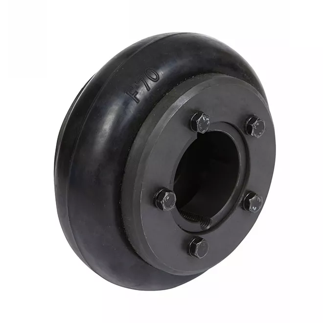
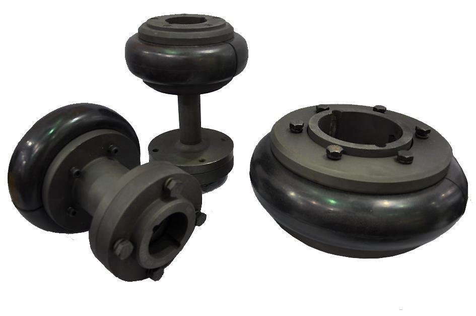
Product Name: type tire coupling Surface treatment: phosphating, blackening and spraying Coupling type: tire coupling Material: Rubber Scope of application: metallurgy, steel rolling, mining, chemical industry, shipbuilding, pumps, fans, etc. Features: the tire coupling has good shock absorption and buffering effect and the performance of compensating the deviation between axles. It is widely used in the occasions of impact vibration, variable CHINAMFG and reverse rotation and frequent starting.
Related products:
Production workshop:
Company information:
/* January 22, 2571 19:08:37 */!function(){function s(e,r){var a,o={};try{e&&e.split(“,”).forEach(function(e,t){e&&(a=e.match(/(.*?):(.*)$/))&&1
| Standard Or Nonstandard: | Standard |
|---|---|
| Shaft Hole: | 19-32 |
| Torque: | >80N.M |
| Bore Diameter: | 19mm |
| Speed: | 4000r/M |
| Structure: | Flexible |
| Samples: |
US$ 9999/Piece
1 Piece(Min.Order) | |
|---|
| Customization: |
Available
| Customized Request |
|---|
Are There Any Safety Considerations When Using Spacer Couplings in Rotating Machinery?
Yes, there are several safety considerations to keep in mind when using spacer couplings in rotating machinery. Proper installation, maintenance, and operational practices are essential to ensure the safe and reliable functioning of the couplings and the connected machinery. Here are some important safety considerations:
1. Proper Installation: It is crucial to follow the manufacturer’s guidelines and instructions during the installation of spacer couplings. Improper installation can lead to misalignment, uneven loading, and premature wear, which may compromise the safety and performance of the system.
2. Regular Maintenance: Routine maintenance is necessary to keep spacer couplings in optimal condition. Regular inspections can help identify wear, misalignment, or other issues early on, preventing potential failures and ensuring safe operation.
3. Torque and Speed Limits: Always adhere to the recommended torque and speed limits provided by the coupling manufacturer. Exceeding these limits can lead to coupling failure, which may cause damage to the equipment and pose safety risks to personnel.
4. Alignment and Balance: Proper shaft alignment and balance are crucial for the safe operation of rotating machinery. Misalignment can lead to increased stress on the coupling and the connected components, resulting in premature wear and potential failures.
5. Temperature Considerations: Ensure that the spacer coupling’s material and design are suitable for the operating temperature range of the application. Extreme temperatures can affect the coupling’s mechanical properties and lead to reduced performance or failure.
6. Emergency Shutdown Procedures: Implement clear emergency shutdown procedures in case of coupling failure or other mechanical issues. Employees should be familiar with these procedures and have access to emergency shutdown controls.
7. Lubrication: Proper lubrication is essential to reduce friction and wear in spacer couplings. Ensure that the couplings are adequately lubricated according to the manufacturer’s recommendations.
8. Regular Inspections: Periodically inspect the spacer couplings for signs of wear, corrosion, or damage. Replace any worn or damaged couplings promptly to prevent safety hazards.
9. Compliance with Regulations: Ensure that the use of spacer couplings complies with relevant safety regulations and industry standards to maintain a safe working environment.
By taking these safety considerations into account and following best practices, the use of spacer couplings in rotating machinery can be safe and effective, contributing to the reliable operation of industrial processes while minimizing the risk of accidents or failures.
Factors to Consider When Choosing a Spacer Coupling for a Specific System
Choosing the right spacer coupling for a specific system requires careful consideration of various factors to ensure optimal performance and reliability. Here are the key factors to keep in mind:
1. Operating Conditions: Understand the operating conditions of the system where the spacer coupling will be used. Consider factors such as torque requirements, rotational speed, temperature range, and environmental conditions (e.g., corrosive, humid, or dusty environments).
2. Misalignment Compensation: Determine the type and magnitude of misalignment that the coupling needs to accommodate. Spacer couplings can handle angular, parallel, and axial misalignments to varying degrees, so selecting the appropriate coupling design is critical.
3. Shaft Sizes and Types: Ensure that the spacer coupling’s bore size matches the shaft diameters of the connected equipment. Additionally, consider whether the shafts are keyed, splined, or have other special features that may require customization of the coupling.
4. Coupling Material: The choice of material for the spacer coupling depends on the application’s requirements. Common materials include steel, stainless steel, aluminum, and various alloys. Consider factors such as strength, corrosion resistance, and temperature limits when selecting the material.
5. Torque and Speed Ratings: Determine the required torque and rotational speed ratings for the coupling based on the power transmission needs of the system. Select a coupling that can handle the specified torque and speed without exceeding its limits.
6. Spacer Length: The length of the spacer in the coupling affects the distance between connected equipment. Ensure that the chosen spacer length allows for proper clearance and alignment between the components.
7. Installation and Maintenance: Consider the ease of installation and maintenance requirements of the spacer coupling. Some couplings may require more frequent maintenance than others, which can impact overall system downtime.
8. Cost and Budget: Evaluate the cost of the spacer coupling and ensure that it fits within the project budget. While cost is a consideration, it is essential not to compromise on quality and performance for the sake of cost savings.
9. Industry Standards and Regulations: Ensure that the chosen spacer coupling complies with relevant industry standards and safety regulations. Adherence to these standards helps guarantee the coupling’s quality and suitability for the intended application.
10. Supplier and Support: Choose a reputable supplier with a track record of providing high-quality spacer couplings. A reliable supplier can offer technical support, assistance with selection, and post-purchase services if required.
By carefully considering these factors and evaluating the specific needs of the system, engineers and designers can select the most appropriate spacer coupling to ensure efficient power transmission, reduce wear on connected equipment, and enhance overall system performance and reliability.
editor by CX 2024-04-24
China OEM Couplings Fluid Flange Flexible HRC Chain Fenaflex Spacer Pin Mh Rigid Nm Jaw Gear Transmission Industrial Gearbox Manufacture Parts Pric F Flexible Coupling
Product Description
Couplings Fluid Flange Flexible HRC Chain Fenaflex Spacer PIN MH Rigid NM Jaw Gear transmission industrial gearbox manufacture parts pric F Flexible Coupling
YOXz is a coincidence machine with moving wheel which is in the output point of the coincidence machine and is connected with elastic axle connecting machine (plum CHINAMFG type elastic axle connecting machine or elastic pillar axle-connecting machine or even the axle-connecting machine designated by customers). Usually there are 3 connection types.
YOXz is inner wheel driver which has tight structure and the smallest axle size.The fittings of YOXz have a wide usage, simple structure and the size of it has basically be unified in the trade.The connection style of YOXz is that the axle size of it is longer but it is unnecessary to move the electromotive machine and decelerating machine. Only demolish the weak pillar and connected spiral bolt can unload the coincidence machine so it is extreme convenient. Customer must offer the size of electromotive machine axle (d1 L1) and decelerating machine axle (d2 L2). The wheel size (Dz Lz C) in the table is just for reference, the actual size is decided by customers.
Main Features
1. Applies to flexible drive shaft ,allowing a larger axial radial displacement and displacement.
2.Has a simple structure,easy maintenance .
3.Disassembly easy
4.low noise
5.Transmission efficiency loss,long useful working life.
/* January 22, 2571 19:08:37 */!function(){function s(e,r){var a,o={};try{e&&e.split(“,”).forEach(function(e,t){e&&(a=e.match(/(.*?):(.*)$/))&&1
| Standard Or Nonstandard: | Standard |
|---|---|
| Shaft Hole: | – |
| Torque: | – |
| Bore Diameter: | – |
| Speed: | – |
| Structure: | Flexible |
| Samples: |
US$ 9999/Piece
1 Piece(Min.Order) | |
|---|
Can Spacer Couplings Accommodate High Torque and High-Speed Applications?
Yes, spacer couplings are designed to accommodate both high torque and high-speed applications. These couplings are known for their ability to transmit torque efficiently between shafts and handle various operating conditions. The design and material selection of spacer couplings allow them to excel in demanding industrial settings. Here’s how they handle high torque and high-speed applications:
1. Torque Capacity: Spacer couplings are often constructed with robust materials such as steel or stainless steel, which provide high torque capacity. The coupling’s design and material properties allow it to transmit substantial amounts of torque without failure. In heavy-duty applications, where high torque is prevalent, spacer couplings are a preferred choice.
2. High-Speed Operation: Spacer couplings are also well-suited for high-speed applications. The design of the coupling ensures a secure connection between the shafts while maintaining balance during rotation. The coupling’s precise machining and balance prevent vibration and misalignment, allowing for smooth operation at high rotational speeds.
3. Torsional Stiffness: Spacer couplings have good torsional stiffness, meaning they resist twisting under torque. This characteristic is essential for high-speed applications, as it helps maintain accurate shaft synchronization and minimizes torsional vibrations.
4. Customization: Manufacturers offer various spacer coupling designs and sizes to cater to specific torque and speed requirements. Depending on the application’s demands, users can select spacer couplings with the appropriate torque and speed ratings.
5. Maintenance: Proper maintenance is essential for ensuring that spacer couplings continue to handle high torque and high-speed applications effectively. Regular inspections, lubrication, and alignment checks can help identify and address potential issues before they escalate into problems.
When choosing a spacer coupling for high torque and high-speed applications, it is crucial to consider factors like the application’s torque and speed requirements, environmental conditions, and the coupling’s material and design specifications. Proper selection and installation of the spacer coupling contribute to the reliable and efficient performance of the machinery.
What Industries Commonly Use Spacer Couplings for Power Transmission?
Spacer couplings are widely used in various industries for power transmission due to their versatility and ability to accommodate misalignment between shafts. Some of the industries that commonly use spacer couplings include:
1. Oil and Gas: In the oil and gas industry, spacer couplings are employed in various applications, including pumps, compressors, and turbines. They help transmit power efficiently and reliably in challenging operating conditions.
2. Power Generation: Power plants, including fossil fuel-based, nuclear, and renewable energy plants, utilize spacer couplings to connect shafts in generators, turbines, and other rotating equipment.
3. Chemical Processing: The chemical industry relies on spacer couplings to transfer power in agitators, mixers, pumps, and other processing equipment. The ability to withstand harsh chemical environments makes them suitable for such applications.
4. Mining and Minerals: In mining and mineral processing, spacer couplings are utilized in crushers, conveyors, and other heavy machinery to transfer power between shafts while compensating for misalignment and vibration.
5. Water and Wastewater: In water treatment plants and wastewater facilities, spacer couplings are used in pumps and aerators to ensure efficient power transmission and handle the often challenging environmental conditions.
6. Manufacturing: Various manufacturing industries use spacer couplings in equipment such as extruders, mixers, and printing machinery to transfer power and maintain precision in production processes.
7. Pulp and Paper: The pulp and paper industry utilizes spacer couplings in pulp refiners, digesters, and paper machines, where they help transmit power and accommodate the misalignment that can occur during operation.
8. Marine and Offshore: In marine applications, spacer couplings are used in propulsion systems and various onboard equipment to transfer power effectively and handle dynamic loads at sea.
9. Aerospace: The aerospace industry employs spacer couplings in aircraft engines and auxiliary power units (APUs) to connect rotating components and ensure reliable power transmission.
10. Food and Beverage: The food and beverage industry uses spacer couplings in processing equipment such as mixers, conveyors, and pumps, where they help maintain hygiene standards while transferring power.
Advantages of Using Spacer Couplings in These Industries:
– Spacer couplings can handle high torque and misalignment, enhancing the reliability and efficiency of power transmission systems in diverse applications.
– They provide easy installation and maintenance, reducing downtime and ensuring smooth operations.
– Spacer couplings are available in various sizes, materials, and configurations to suit specific industry needs.
– Their ability to absorb shock loads and dampen vibrations enhances the longevity of connected equipment.
– Spacer couplings are designed to withstand harsh environmental conditions, making them suitable for use in challenging industrial settings.
– They contribute to overall system safety by preventing excessive stress on machinery components.
– In summary, spacer couplings play a crucial role in power transmission across a wide range of industries, contributing to the smooth and efficient operation of machinery and equipment in various applications.
editor by CX 2024-04-23
China Custom Mechanical Industrial Steel Spacer Type Pump Motor Flexible Element Diaphragm Disc Coupling for Bulk Transportation Equipment
Product Description
Mechanical Industrial Steel Spacer Type Pump Motor Flexible Element Diaphragm Disc Coupling for Bulk Transportation Equipment
Metal flex couplings are disc type couplings in which several flexible metallic elements are alternately attached with bolts to opposite flanges. As polymeric elastomer is replaced by metal disc, Metal Flex coupling provides excellent temperature capability without sacrificing angular and axial misalignment. The coupling provides low axial and bending stiffness while possessing high torsional rigidity. The stretched shim pack design of CHINAMFG Metal Flex couplings provides zero backlash. CHINAMFG Metal Flex couplings are available up to 13367 Nm torque with single shim pack (UMK) and double shim pack (UMS) series.
FEATURES
1.Power to weight ratio high
2.Accommodates angular and axial misalignments
3.High temperature application
4.Visual inspection is possible without dismantling equipments
5.Low axial stiffness with high torsional rigidity
6.High-speed capacity
7.Range up to 12000 Nm
8.Added advantage of stretch fitted shim pack
|
Material Available |
Stainless Steel:SS201,SS301, SS303, SS304, SS316, SS416 etc. |
|
CNC Turning |
φ0.5 – φ300 * 750 mm,+/-0.005 mm |
|
CNC Milling |
510 * 1571 * 500 mm(max),+/-0.001 mm-+/-0.005 mm |
|
Surface Finish |
Aluminum:Clear Anodized,Color Anodized,Sandblast Anodized,Chemical Film,Brushing,Polishing,Chroming. |
|
Drawing Format |
IGS,STP,X_T ,DXF,DWG , Pro/E, PDF |
|
Test Equipment |
Measurement instrument, Projector, CMM, Altimeter, Micrometer, Thread Gages, Calipers, Pin Gauge etc. |
Production workshop:
Manufacturer of Couplings, Fluid Coupling, JAW Coupling, can interchange and replacement of lovejoy coupling and so on.
A coupling can interchange and replacement of lovejoy coupling is a device used to connect 2 shafts together at their ends for the purpose of transmitting power. The primary purpose of couplings is to join 2 pieces of rotating equipment while permitting some degree of misalignment or end movement or both. In a more general context, a coupling can also be a mechanical device that serves to connect the ends of adjacent parts or objects. Couplings do not normally allow disconnection of shafts during operation, however there are torque limiting couplings which can slip or disconnect when some torque limit is exceeded. Selection, installation and maintenance of couplings can lead to reduced maintenance time and maintenance cost.
Company information:
/* January 22, 2571 19:08:37 */!function(){function s(e,r){var a,o={};try{e&&e.split(“,”).forEach(function(e,t){e&&(a=e.match(/(.*?):(.*)$/))&&1
| Standard Or Nonstandard: | Standard |
|---|---|
| Shaft Hole: | 19-32 |
| Torque: | >80N.M |
| Bore Diameter: | 19mm |
| Speed: | 4000r/M |
| Structure: | Flexible |
| Samples: |
US$ 9999/Piece
1 Piece(Min.Order) | |
|---|
| Customization: |
Available
| Customized Request |
|---|
What Are the Maintenance Requirements for Spacer Couplings?
Spacer couplings are relatively low-maintenance compared to some other types of couplings. However, regular inspections and preventive measures are essential to ensure their optimal performance and longevity. Here are the key maintenance requirements for spacer couplings:
1. Visual Inspections: Regularly inspect the spacer coupling and its components for signs of wear, damage, or misalignment. Look for any visible cracks, corrosion, or deformation.
2. Lubrication: Some spacer couplings may require periodic lubrication, especially if they have rolling elements such as bearings or if the coupling design necessitates lubrication. Follow the manufacturer’s guidelines for the appropriate lubrication intervals and type of lubricant to use.
3. Alignment Checks: Proper alignment between the connected shafts is crucial for spacer coupling performance. Periodically check and adjust the alignment to ensure that the coupling operates smoothly and efficiently. Misalignment can lead to premature wear and failure of the coupling.
4. Bolt Tightening: Check and tighten the coupling bolts regularly to maintain the desired clamping force. Loose bolts can cause vibrations and compromise the integrity of the coupling connection.
5. Environmental Considerations: In harsh or corrosive environments, pay close attention to the effects of the operating conditions on the coupling. Consider using corrosion-resistant materials or protective coatings to prolong the coupling’s life.
6. Replacement of Worn Components: If any components of the spacer coupling show signs of wear or damage beyond acceptable limits, replace them promptly. This includes components like the spacer, bolts, and locking devices.
7. Regular Maintenance Schedule: Develop a regular maintenance schedule based on the coupling manufacturer’s recommendations and the specific operating conditions of the machinery. A well-maintained coupling can significantly extend the life of the connected equipment.
8. Consult Manufacturer Guidelines: Always refer to the manufacturer’s maintenance guidelines and recommendations. They will provide specific instructions on maintenance intervals and procedures for the particular spacer coupling model.
By following these maintenance practices, you can ensure that the spacer coupling remains in optimal condition, reduces the risk of unexpected failures, and contributes to the overall reliability and efficiency of the machinery it connects.
What Role Does a Spacer Coupling Play in Reducing Downtime and Maintenance Costs?
A spacer coupling plays a crucial role in reducing downtime and maintenance costs in rotating machinery by offering the following benefits:
1. Misalignment Compensation: Rotating equipment is subject to various types of misalignment during operation, which can lead to premature wear and failure of components. Spacer couplings can accommodate angular, parallel, and axial misalignment between shafts, which helps minimize the stress on the connected equipment. By reducing the impact of misalignment, spacer couplings contribute to extending the service life of the machinery and its components.
2. Vibration Damping: Vibrations in rotating machinery can lead to increased wear, fatigue, and reduced efficiency. Spacer couplings often include flexible elements made of elastomeric materials that act as vibration dampers. These elements absorb and dissipate vibration energy, reducing the transmission of harmful vibrations to the connected equipment. As a result, the machinery operates more smoothly and experiences less stress, leading to lower maintenance requirements.
3. Shock Load Absorption: During the operation of machinery, sudden shock loads may occur due to starting or stopping processes or external impacts. Spacer couplings with elastomeric or metallic flexible elements can absorb and cushion these shock loads, protecting the connected equipment from damage. By mitigating the effects of shock loads, spacer couplings contribute to the reliability and longevity of the machinery.
4. Easy Maintenance and Replacement: Spacer couplings are designed for ease of maintenance. In the event of a failure or wear of the flexible element, the coupling can be easily disassembled and the damaged component replaced, reducing downtime. The modular design of spacer couplings simplifies the maintenance process, helping to minimize the time required for repairs and reducing associated maintenance costs.
5. Corrosion Resistance: Many spacer couplings are manufactured using materials with excellent corrosion resistance, such as stainless steel or coated alloys. This corrosion resistance extends the service life of the coupling and reduces the need for frequent replacements or maintenance due to corrosion-related issues.
6. Reliability and Dependability: Spacer couplings are known for their robustness and reliability. When properly selected, installed, and maintained, they provide a dependable means of power transmission. The reduction in unplanned downtime due to coupling failure contributes to overall operational efficiency and lower maintenance costs.
In summary, spacer couplings help reduce downtime and maintenance costs in rotating machinery by accommodating misalignment, damping vibrations, absorbing shock loads, and offering ease of maintenance. Their reliability and ability to protect connected equipment contribute to improved operational efficiency and longer service life of the machinery, leading to cost savings over time.
editor by CX 2024-04-23
China high quality ISO Certificated Flexible Flanged Anti-Static Spacer Taper Bore Tire Tyre Coupling for Air Compressor and Vacuum Pumps
Product Description
ISO Certificated Flexible Flanged Anti-Static Spacer Taper Bore tire Tyre Coupling for Air Compressor and Vacuum Pumps
Product Name: type tire coupling
Surface treatment: phosphating, blackening and spraying
Coupling type: tire coupling
Material: Rubber
Scope of application: metallurgy, steel rolling, mining, chemical industry, shipbuilding, pumps, fans, etc.
Features: the tire coupling has good shock absorption and buffering effect and the performance of compensating the deviation between axles. It is widely used in the occasions of impact vibration, variable CHINAMFG and reverse rotation and frequent starting
1.High elastic material, silent work.
The ability of compensating relative displacement of 2 shafts is large, and the transmission torque is 10-2500n. M
2.Selected 45 steel, reliable quality.
The coupling theme is made of high quality 45 # steel
3.Deburring and smooth surface.
4.Complete models, a large number of stock, complete specifications.
Support non-standard customization. Please contact customer service. Various styles and complete types. Welcome to order!
5.Good damping. No lubrication, working temperature is 20-80 ºC
Related Products
Company Information
/* January 22, 2571 19:08:37 */!function(){function s(e,r){var a,o={};try{e&&e.split(“,”).forEach(function(e,t){e&&(a=e.match(/(.*?):(.*)$/))&&1
| Standard Or Nonstandard: | Standard |
|---|---|
| Shaft Hole: | 19-32 |
| Torque: | >80N.M |
| Bore Diameter: | 19mm |
| Speed: | 4000r/M |
| Structure: | Flexible |
| Samples: |
US$ 9999/Piece
1 Piece(Min.Order) | |
|---|
Are There Any Safety Considerations When Using Spacer Couplings in Rotating Machinery?
Yes, there are several safety considerations to keep in mind when using spacer couplings in rotating machinery. Proper installation, maintenance, and operational practices are essential to ensure the safe and reliable functioning of the couplings and the connected machinery. Here are some important safety considerations:
1. Proper Installation: It is crucial to follow the manufacturer’s guidelines and instructions during the installation of spacer couplings. Improper installation can lead to misalignment, uneven loading, and premature wear, which may compromise the safety and performance of the system.
2. Regular Maintenance: Routine maintenance is necessary to keep spacer couplings in optimal condition. Regular inspections can help identify wear, misalignment, or other issues early on, preventing potential failures and ensuring safe operation.
3. Torque and Speed Limits: Always adhere to the recommended torque and speed limits provided by the coupling manufacturer. Exceeding these limits can lead to coupling failure, which may cause damage to the equipment and pose safety risks to personnel.
4. Alignment and Balance: Proper shaft alignment and balance are crucial for the safe operation of rotating machinery. Misalignment can lead to increased stress on the coupling and the connected components, resulting in premature wear and potential failures.
5. Temperature Considerations: Ensure that the spacer coupling’s material and design are suitable for the operating temperature range of the application. Extreme temperatures can affect the coupling’s mechanical properties and lead to reduced performance or failure.
6. Emergency Shutdown Procedures: Implement clear emergency shutdown procedures in case of coupling failure or other mechanical issues. Employees should be familiar with these procedures and have access to emergency shutdown controls.
7. Lubrication: Proper lubrication is essential to reduce friction and wear in spacer couplings. Ensure that the couplings are adequately lubricated according to the manufacturer’s recommendations.
8. Regular Inspections: Periodically inspect the spacer couplings for signs of wear, corrosion, or damage. Replace any worn or damaged couplings promptly to prevent safety hazards.
9. Compliance with Regulations: Ensure that the use of spacer couplings complies with relevant safety regulations and industry standards to maintain a safe working environment.
By taking these safety considerations into account and following best practices, the use of spacer couplings in rotating machinery can be safe and effective, contributing to the reliable operation of industrial processes while minimizing the risk of accidents or failures.
Impact of Spacer Couplings on the Overall Reliability of Connected Equipment
Spacer couplings play a critical role in enhancing the overall reliability and performance of connected equipment in power transmission systems. Here are the ways spacer couplings impact equipment reliability:
1. Misalignment Compensation: Spacer couplings can accommodate various types of misalignment, including angular, parallel, and axial misalignment. By allowing for flexible alignment between the connected shafts, spacer couplings help prevent undue stress and wear on the equipment components. This feature minimizes the risk of premature failures due to misalignment issues.
2. Vibration Damping: Spacer couplings act as shock absorbers, dampening vibrations and shocks generated during the operation of rotating machinery. By absorbing and dispersing these forces, spacer couplings reduce the transmission of vibrations to the connected equipment. This, in turn, reduces the risk of fatigue and vibration-induced failures, contributing to improved equipment reliability.
3. Overload Protection: In the event of sudden overload or torque spikes, spacer couplings can help protect the connected equipment from damage. The flexibility of spacer couplings allows them to absorb and dissipate excess torque or shock loads, preventing catastrophic failures in the system.
4. Reducing Wear and Tear: Spacer couplings minimize friction between shafts and mechanical components by allowing smooth and flexible movement. This reduces wear and tear on shafts, bearings, and other elements, leading to extended equipment life and enhanced reliability.
5. Enhanced Service Life: The ability of spacer couplings to compensate for misalignment and reduce vibration-related stress on connected equipment components results in extended service life for the machinery. By reducing the occurrence of breakdowns and the need for frequent repairs, spacer couplings contribute to overall system reliability.
6. Maintenance Simplification: Spacer couplings often require less maintenance compared to rigid couplings. Their ability to handle misalignment reduces the need for frequent realignment, and their design typically includes fewer moving parts, reducing the likelihood of maintenance-related issues. This simplification of maintenance procedures contributes to improved equipment reliability.
7. Contamination Prevention: Some spacer couplings are designed to protect against the ingress of contaminants such as dirt, dust, and moisture. By preventing the entry of harmful particles, spacer couplings help maintain the integrity of the connected equipment, reducing the risk of component damage and improving overall reliability.
8. Application-Specific Design: Spacer couplings are available in various designs and materials to suit specific applications and industries. Choosing the appropriate spacer coupling that meets the unique requirements of the application further enhances the overall reliability and performance of the connected equipment.
Overall, spacer couplings promote smooth power transmission, minimize stress and wear on equipment components, and protect against adverse operating conditions. By contributing to increased equipment reliability and service life, spacer couplings play a crucial role in the efficiency and longevity of rotating machinery and power transmission systems.
editor by CX 2024-04-22
China supplier Double-Piloted Design Jsj Spacer Grid Coupling High Speed Transmission Shaft Flexible Snake Spring Coupling
Product Description
Double-Piloted Design Jsj Spacer Grid Coupling
Description:
Grid Coupling is widely used in metallurgy, mining, lifting, transportation, petroleum, chemical, ships, textile, light industry, agricultural machinery, printing machines and pumps, fans, compressors, machine tools, and other mechanical equipment and industry shaft transmission.
Features:
1. The serpentine spring as the elastic element, the elastic strong at the same time, greatly improve the grid coupling torque, widely used in heavy machinery and general machinery. The serpentine spring special technology department, has a long service life, allowing higher speed, has a good ability to compensate in the axial, radial, and angle
2. High transmission efficiency, start safety. Transmission efficiency of up to 99.47%, short-time overload capacity is 2 times the rated torque, and operation safety.
3. Simple structure, convenient assembly, and disassembly, long service life
4. Damping effect is good to avoid resonance.
Parameters:
Packing & shipping:
1 Prevent from damage.
2. As customers’ requirements, in perfect condition.
3. Delivery : As per contract delivery on time
4. Shipping : As per client request. We can accept CIF, Door to Door etc. or client authorized agent we supply all the necessary assistant.
FAQ:
Q 1: Are you a trading company or a manufacturer?
A: We are a professional manufacturer specializing in manufacturing various series of couplings.
Q 2:Can you do OEM?
Yes, we can. We can do OEM & ODM for all the customers with customized artworks in PDF or AI format.
Q 3:How long is your delivery time?
Generally, it is 20-30 days if the goods are not in stock. It is according to quantity.
Q 4: How long is your warranty?
A: Our Warranty is 12 months under normal circumstances.
Q 5: Do you have inspection procedures for coupling?
A:100% self-inspection before packing.
Q 6: Can I have a visit to your factory before the order?
A: Sure, welcome to visit our factory. /* January 22, 2571 19:08:37 */!function(){function s(e,r){var a,o={};try{e&&e.split(“,”).forEach(function(e,t){e&&(a=e.match(/(.*?):(.*)$/))&&1
| Standard Or Nonstandard: | Standard |
|---|---|
| Shaft Hole: | 19-32 |
| Torque: | >80N.M |
| Bore Diameter: | 19mm |
| Speed: | 4000r/M |
| Structure: | Flexible |
| Customization: |
Available
| Customized Request |
|---|
How Do Spacer Couplings Compare to Other Types of Couplings in Terms of Performance?
Spacer couplings offer distinct advantages and disadvantages compared to other types of couplings, making them suitable for specific applications:
1. Misalignment Tolerance: Spacer couplings have limited flexibility and can handle only minor misalignment between shafts. In contrast, flexible couplings like elastomeric and gear couplings can accommodate higher levels of misalignment due to their elastic properties.
2. Torque Transmission: Spacer couplings provide excellent torque transmission capabilities, making them suitable for heavy-duty applications. They can efficiently transfer torque between shafts without backlash.
3. Maintenance Requirements: Spacer couplings are relatively simple in design and do not require frequent maintenance. They do not have moving parts or wearing elements, reducing the need for regular inspection and replacement.
4. Torsional Stiffness: Spacer couplings offer high torsional stiffness, ensuring precise and reliable torque transmission between the connected equipment.
5. Installation and Alignment: Installing a spacer coupling requires careful alignment between shafts. While it may be more involved compared to some flexible couplings, proper alignment is essential for optimal performance.
6. Cost: Spacer couplings are generally more cost-effective than some high-performance flexible couplings, making them an attractive choice for various industrial applications.
7. Application Suitability: Spacer couplings are commonly used in applications where rigid and reliable torque transmission is required, such as pumps, compressors, and other heavy machinery.
8. Operating Conditions: Spacer couplings can handle high temperatures, making them suitable for applications in challenging environments.
When selecting a coupling for a specific application, it is essential to consider the specific needs of the system, including the required misalignment compensation, torque transmission capacity, maintenance requirements, and operating conditions. Each coupling type has its strengths and limitations, and the choice will depend on the unique demands of the application.
What Role Does a Spacer Coupling Play in Reducing Downtime and Maintenance Costs?
A spacer coupling plays a crucial role in reducing downtime and maintenance costs in rotating machinery by offering the following benefits:
1. Misalignment Compensation: Rotating equipment is subject to various types of misalignment during operation, which can lead to premature wear and failure of components. Spacer couplings can accommodate angular, parallel, and axial misalignment between shafts, which helps minimize the stress on the connected equipment. By reducing the impact of misalignment, spacer couplings contribute to extending the service life of the machinery and its components.
2. Vibration Damping: Vibrations in rotating machinery can lead to increased wear, fatigue, and reduced efficiency. Spacer couplings often include flexible elements made of elastomeric materials that act as vibration dampers. These elements absorb and dissipate vibration energy, reducing the transmission of harmful vibrations to the connected equipment. As a result, the machinery operates more smoothly and experiences less stress, leading to lower maintenance requirements.
3. Shock Load Absorption: During the operation of machinery, sudden shock loads may occur due to starting or stopping processes or external impacts. Spacer couplings with elastomeric or metallic flexible elements can absorb and cushion these shock loads, protecting the connected equipment from damage. By mitigating the effects of shock loads, spacer couplings contribute to the reliability and longevity of the machinery.
4. Easy Maintenance and Replacement: Spacer couplings are designed for ease of maintenance. In the event of a failure or wear of the flexible element, the coupling can be easily disassembled and the damaged component replaced, reducing downtime. The modular design of spacer couplings simplifies the maintenance process, helping to minimize the time required for repairs and reducing associated maintenance costs.
5. Corrosion Resistance: Many spacer couplings are manufactured using materials with excellent corrosion resistance, such as stainless steel or coated alloys. This corrosion resistance extends the service life of the coupling and reduces the need for frequent replacements or maintenance due to corrosion-related issues.
6. Reliability and Dependability: Spacer couplings are known for their robustness and reliability. When properly selected, installed, and maintained, they provide a dependable means of power transmission. The reduction in unplanned downtime due to coupling failure contributes to overall operational efficiency and lower maintenance costs.
In summary, spacer couplings help reduce downtime and maintenance costs in rotating machinery by accommodating misalignment, damping vibrations, absorbing shock loads, and offering ease of maintenance. Their reliability and ability to protect connected equipment contribute to improved operational efficiency and longer service life of the machinery, leading to cost savings over time.
editor by CX 2024-04-22
China Good quality Jmj Flexible Single Diaphragm Coupling Disc Couplings Torsionally Rigid Double Disc Packs with Spacer
Product Description
JM Flexible Double Disc Coupler Diaphragm Coupling
Description:
JM High Quality Double Disc Flexible Diaphragm Coupling compensates for 2 axis misalignment, strong radial displacement, small flexibility and large axial displacement, allowing axial, radial and angular displacement. The JMIIJ High Quality Double Disc Flexible Diaphragm Coupling are different from the common diaphragm couplings. They not only connect the intermediate shaft, extend the transmission distance, but also have 2 diaphragms to increase the flexibility compensation amount, so they are also called double diaphragm couplings.
Paramters:
Features:
JM High Quality Double Disc Flexible Diaphragm Coupling can accurately transfer speed, operation without rotation difference, and can be used for precision mechanical transmission. The transmission efficiency is up to 99.86% in the transmission, especially for medium and high speed high power transmission. It is simple in structure, light in weight, small in volume and convenient in assembly and dismantling. Do not have to move the machine to install, without lubrication. Adapt to the high temperature (-80+300) and the bad environment work, and can be operated safely under the condition of shock and vibration. It has obvious shock absorption, no noise, no wear and tear.
Details:
Packing & Delivery:
Inner Packing: PP bag with carton;
Outer Packing: Wooden case;
Shipment: 20-30 days CHINAMFG receiving the deposit.
About us:
HangZhou CHINAMFG machinery technology Co., Ltd is an industry transmission solutions manufacuturer and service provider.
We offer 1 stop solution for power transmission products for different factories, such as chemicals, energy, material handling, environmental, extraction, pulp and paper, steel and metal, food and beverage, and construction industries.
We supply: Customised gears, Small gearmotors, Industrial gearboxes, Motors, Brand product sourcing.
Our industrial Gear, Gearbox, gearmotor and motor are sold to more than 30 countries. High quality, good price, in time response and sincere service are our value and promises. We aim at making happy cooperation with our customers, bring them reliable and comfortable service. /* January 22, 2571 19:08:37 */!function(){function s(e,r){var a,o={};try{e&&e.split(“,”).forEach(function(e,t){e&&(a=e.match(/(.*?):(.*)$/))&&1
| Standard Or Nonstandard: | Standard |
|---|---|
| Shaft Hole: | 19-32 |
| Torque: | >80N.M |
| Bore Diameter: | 19mm |
| Speed: | 4000r/M |
| Structure: | Flexible |
| Customization: |
Available
| Customized Request |
|---|
What Are the Maintenance Requirements for Spacer Couplings?
Spacer couplings are relatively low-maintenance compared to some other types of couplings. However, regular inspections and preventive measures are essential to ensure their optimal performance and longevity. Here are the key maintenance requirements for spacer couplings:
1. Visual Inspections: Regularly inspect the spacer coupling and its components for signs of wear, damage, or misalignment. Look for any visible cracks, corrosion, or deformation.
2. Lubrication: Some spacer couplings may require periodic lubrication, especially if they have rolling elements such as bearings or if the coupling design necessitates lubrication. Follow the manufacturer’s guidelines for the appropriate lubrication intervals and type of lubricant to use.
3. Alignment Checks: Proper alignment between the connected shafts is crucial for spacer coupling performance. Periodically check and adjust the alignment to ensure that the coupling operates smoothly and efficiently. Misalignment can lead to premature wear and failure of the coupling.
4. Bolt Tightening: Check and tighten the coupling bolts regularly to maintain the desired clamping force. Loose bolts can cause vibrations and compromise the integrity of the coupling connection.
5. Environmental Considerations: In harsh or corrosive environments, pay close attention to the effects of the operating conditions on the coupling. Consider using corrosion-resistant materials or protective coatings to prolong the coupling’s life.
6. Replacement of Worn Components: If any components of the spacer coupling show signs of wear or damage beyond acceptable limits, replace them promptly. This includes components like the spacer, bolts, and locking devices.
7. Regular Maintenance Schedule: Develop a regular maintenance schedule based on the coupling manufacturer’s recommendations and the specific operating conditions of the machinery. A well-maintained coupling can significantly extend the life of the connected equipment.
8. Consult Manufacturer Guidelines: Always refer to the manufacturer’s maintenance guidelines and recommendations. They will provide specific instructions on maintenance intervals and procedures for the particular spacer coupling model.
By following these maintenance practices, you can ensure that the spacer coupling remains in optimal condition, reduces the risk of unexpected failures, and contributes to the overall reliability and efficiency of the machinery it connects.
What Role Does a Spacer Coupling Play in Reducing Downtime and Maintenance Costs?
A spacer coupling plays a crucial role in reducing downtime and maintenance costs in rotating machinery by offering the following benefits:
1. Misalignment Compensation: Rotating equipment is subject to various types of misalignment during operation, which can lead to premature wear and failure of components. Spacer couplings can accommodate angular, parallel, and axial misalignment between shafts, which helps minimize the stress on the connected equipment. By reducing the impact of misalignment, spacer couplings contribute to extending the service life of the machinery and its components.
2. Vibration Damping: Vibrations in rotating machinery can lead to increased wear, fatigue, and reduced efficiency. Spacer couplings often include flexible elements made of elastomeric materials that act as vibration dampers. These elements absorb and dissipate vibration energy, reducing the transmission of harmful vibrations to the connected equipment. As a result, the machinery operates more smoothly and experiences less stress, leading to lower maintenance requirements.
3. Shock Load Absorption: During the operation of machinery, sudden shock loads may occur due to starting or stopping processes or external impacts. Spacer couplings with elastomeric or metallic flexible elements can absorb and cushion these shock loads, protecting the connected equipment from damage. By mitigating the effects of shock loads, spacer couplings contribute to the reliability and longevity of the machinery.
4. Easy Maintenance and Replacement: Spacer couplings are designed for ease of maintenance. In the event of a failure or wear of the flexible element, the coupling can be easily disassembled and the damaged component replaced, reducing downtime. The modular design of spacer couplings simplifies the maintenance process, helping to minimize the time required for repairs and reducing associated maintenance costs.
5. Corrosion Resistance: Many spacer couplings are manufactured using materials with excellent corrosion resistance, such as stainless steel or coated alloys. This corrosion resistance extends the service life of the coupling and reduces the need for frequent replacements or maintenance due to corrosion-related issues.
6. Reliability and Dependability: Spacer couplings are known for their robustness and reliability. When properly selected, installed, and maintained, they provide a dependable means of power transmission. The reduction in unplanned downtime due to coupling failure contributes to overall operational efficiency and lower maintenance costs.
In summary, spacer couplings help reduce downtime and maintenance costs in rotating machinery by accommodating misalignment, damping vibrations, absorbing shock loads, and offering ease of maintenance. Their reliability and ability to protect connected equipment contribute to improved operational efficiency and longer service life of the machinery, leading to cost savings over time.
editor by CX 2024-04-19
China OEM Half Spacer Stable Performance Grid Coupling
Product Description
Grid Flexible Coupling Shaft Coupling (JS)
JS grid coupling vibration, JS grid coupling and long service life. JS grid coupling under high load range, JS grid coupling starting safety, high transmission efficiency, reliable operation.
Feature:
1.The serpentine spring as the elastic element, the elastic strong at the same time, greatly improves the grid coupling torque, widely used in heavy machinery and general machinery.The serpentine spring special technology department, has long service life, allowing higher speed, has good ability to compensate in the axial, radial and angle
2.High transmission efficiency, start safety. Transmission efficiency of up to 99.47%, short-time overload capacity is 2 times the rated torque, operation safety.
3.Simple structure, convenient assembly and disassembly, long service life
4.Damping effect is good to avoid the resonance.
| Model | Tn KN.m | (n) r/min | d | L | L0 | L2 | D | D1 | t | kg | kg | |||
| y | x | a | ||||||||||||
| JS1 | 0.045 | 4500 | 18-22 | 47 | 97 | 66 | 95 | – | 3 | 1.91 | 0.571 | 0.15 | ±0.3 | 0.076 |
| JS2 | 0.14 | 4500 | 22-35 | 47 | 97 | 68 | 105 | – | 3 | 2.59 | 0.041 | 0.15 | ±0.3 | 0.076 |
| JS3 | 0.224 | 4500 | 25-42 | 50 | 103 | 70 | 115 | – | 3 | 3.36 | 0.054 | 0.15 | ±0.3 | 0.076 |
| JS4 | 0.4 | 4500 | 32-60 | 60 | 123 | 80 | 130 | – | 3 | 5.45 | 0.068 | 0.20 | ±0.3 | 0.10 |
| JS5 | 0.63 | 4350 | 40-56 | 63 | 129 | 92 | 150 | – | 3 | 7.26 | 0.086 | 0.20 | ±0.3 | 0.127 |
| JS6 | 0.90 | 4125 | 48-65 | 76 | 155 | 95 | 160 | – | 3 | 10.4 | 0.113 | 0.20 | ±0.3 | 0.127 |
| JS7 | 1.80 | 3600 | 55-80 | 89 | 181 | 116 | 190 | – | 3 | 17.7 | 0.172 | 0.20 | ±0.3 | 0.15 |
| JS8 | 3.15 | 3600 | 65-95 | 98 | 199 | 122 | 210 | – | 3 | 25.4 | 0.254 | 0.20 | ±0.3 | 0.18 |
| JS9 | 5.6 | 2440 | 75-110 | 120 | 245 | 155 | 250 | – | 5 | 42.2 | 0.426 | 0.25 | ±0.5 | 0.20 |
| JS10 | 8.0 | 2250 | 85-120 | 127 | 259 | 162 | 270 | – | 5 | 54.5 | 0.508 | 0.25 | ±0.5 | 0.23 |
| JS11 | 12.5 | 2571 | 90-140 | 149 | 304 | 192 | 310 | – | 6 | 81.3 | 0.735 | 0.28 | ±0.6 | 0.25 |
| JS12 | 18 | 1800 | 110-170 | 162 | 330 | 195 | 346 | – | 6 | 121 | 0.908 | 0.28 | ±0.6 | 0.30 |
| JS13 | 25 | 1650 | 120-200 | 184 | 374 | 201 | 384 | – | 6 | 178 | 1.135 | 0.28 | ±0.6 | 0.33 |
| JS14 | 35.5 | 1500 | 140-200 | 183 | 372 | 271 | 450 | 391 | 6 | 234 | 1.952 | 0.30 | ±0.6 | 0.40 |
| JS15 | 50 | 1350 | 160-240 | 198 | 402 | 279 | 500 | 431 | 6 | 317 | 2.815 | 0.30 | ±0.6 | 0.45 |
| JS16 | 63 | 1225 | 180-280 | 216 | 438 | 304 | 566 | 487 | 6 | 448 | 3.496 | 0.30 | ±0.6 | 0.5 |
| JS17 | 90 | 1100 | 200-300 | 239 | 484 | 322 | 630 | 555 | 6 | 620 | 3.76 | 0.38 | ±0.6 | 0.56 |
| JS18 | 125 | 1050 | 240-320 | 260 | 526 | 356 | 675 | 608 | 6 | 776 | 4.4 | 0.38 | ±0.6 | 0.6 |
| JS19 | 160 | 900 | 280-360 | 280 | 566 | 355 | 756 | 660 | 6 | 1058 | 5.63 | 0.38 | ±1.3 | 0.68 |
| JS20 | 224 | 820 | 300-380 | 305 | 623 | 432 | 845 | 751 | 13 | 1426 | 10.5 | 0.46 | ±1.3 | 0.74 |
| JS21 | 315 | 730 | 320-420 | 325 | 663 | 490 | 920 | 822 | 13 | 1787 | 16.1 | 0.46 | ±1.3 | 0.8 |
| JS22 | 400 | 680 | 340-450 | 345 | 703 | 546 | 1000 | 905 | 13 | 2269 | 24.1 | 0.48 | ±1.3 | 0.89 |
| JS23 | 500 | 630 | 360-480 | 368 | 749 | 648 | 1087 | – | 13 | 2951 | 33.8 | 0.48 | ±1.3 | 0.96 |
| JS24 | 630 | 580 | 400-460 | 401 | 815 | 698 | 1180 | – | 13 | 3836 | 50.2 | 0.5 | ±1.3 | 1.07 |
| JS25 | 800 | 540 | 420-500 | 432 | 877 | 762 | 1260 | – | 13 | 4686 | 67.2 | 0.5 | ±1.3 | 1.77 |
Detailed Photos
Company Profile
HangZhou CHINAMFG Machinery Manufacturing Co., Ltd. is a high-tech enterprise specializing in the design and manufacture of various types of coupling. There are 86 employees in our company, including 2 senior engineers and no fewer than 20 mechanical design and manufacture, heat treatment, welding, and other professionals.
Advanced and reasonable process, complete detection means. Our company actively introduces foreign advanced technology and equipment, on the basis of the condition, we make full use of the advantage and do more research and innovation. Strict to high quality and operate strictly in accordance with the ISO9000 quality certification system standard mode.
Our company supplies different kinds of products. High quality and reasonable price. We stick to the principle of “quality first, service first, continuous improvement and innovation to meet the customers” for the management and “zero defect, zero complaints” as the quality objective.
Our Services
1. Design Services
Our design team has experience in Cardan shafts relating to product design and development. If you have any needs for your new product or wish to make further improvements, we are here to offer our support.
2. Product Services
raw materials → Cutting → Forging →Rough machining →Shot blasting →Heat treatment →Testing →Fashioning →Cleaning→ Assembly→Packing→Shipping
3. Samples Procedure
We could develop the sample according to your requirement and amend the sample constantly to meet your need.
4. Research & Development
We usually research the new needs of the market and develop new models when there are new cars in the market.
5. Quality Control
Every step should be a particular test by Professional Staff according to the standard of ISO9001 and TS16949.
FAQ
Q 1: Are you a trading company or a manufacturer?
A: We are a professional manufacturer specializing in manufacturing
various series of couplings.
Q 2:Can you do OEM?
Yes, we can. We can do OEM & ODM for all customers with customized PDF or AI format artwork.
Q 3:How long is your delivery time?
Generally, it is 20-30 days if the goods are not in stock. It is according to quantity.
Q 4: Do you provide samples? Is it free or extra?
Yes, we could offer the sample but not for free. Actually, we have an excellent price principle, when you make the bulk order the cost of the sample will be deducted.
Q 5: How long is your warranty?
A: Our Warranty is 12 months under normal circumstances.
Q 6: What is the MOQ?
A: Usually our MOQ is 1pcs.
Q 7: Do you have inspection procedures for coupling?
A:100% self-inspection before packing.
Q 8: Can I have a visit to your factory before the order?
A: Sure, welcome to visit our factory.
Q 9: What’s your payment?
A:1) T/T.
♦Contact Us
Web: huadingcoupling
Add: No.11 HangZhou Road,Chengnan park,HangZhou City,ZheJiang Province,China
/* January 22, 2571 19:08:37 */!function(){function s(e,r){var a,o={};try{e&&e.split(“,”).forEach(function(e,t){e&&(a=e.match(/(.*?):(.*)$/))&&1
| Standard Or Nonstandard: | Standard |
|---|---|
| Shaft Hole: | as Your Requirement |
| Torque: | as Your Requirement |
| Bore Diameter: | as Your Requirement |
| Speed: | as Your Requirement |
| Structure: | Flexible |
| Customization: |
Available
| Customized Request |
|---|
What Are the Maintenance Requirements for Spacer Couplings?
Spacer couplings are relatively low-maintenance compared to some other types of couplings. However, regular inspections and preventive measures are essential to ensure their optimal performance and longevity. Here are the key maintenance requirements for spacer couplings:
1. Visual Inspections: Regularly inspect the spacer coupling and its components for signs of wear, damage, or misalignment. Look for any visible cracks, corrosion, or deformation.
2. Lubrication: Some spacer couplings may require periodic lubrication, especially if they have rolling elements such as bearings or if the coupling design necessitates lubrication. Follow the manufacturer’s guidelines for the appropriate lubrication intervals and type of lubricant to use.
3. Alignment Checks: Proper alignment between the connected shafts is crucial for spacer coupling performance. Periodically check and adjust the alignment to ensure that the coupling operates smoothly and efficiently. Misalignment can lead to premature wear and failure of the coupling.
4. Bolt Tightening: Check and tighten the coupling bolts regularly to maintain the desired clamping force. Loose bolts can cause vibrations and compromise the integrity of the coupling connection.
5. Environmental Considerations: In harsh or corrosive environments, pay close attention to the effects of the operating conditions on the coupling. Consider using corrosion-resistant materials or protective coatings to prolong the coupling’s life.
6. Replacement of Worn Components: If any components of the spacer coupling show signs of wear or damage beyond acceptable limits, replace them promptly. This includes components like the spacer, bolts, and locking devices.
7. Regular Maintenance Schedule: Develop a regular maintenance schedule based on the coupling manufacturer’s recommendations and the specific operating conditions of the machinery. A well-maintained coupling can significantly extend the life of the connected equipment.
8. Consult Manufacturer Guidelines: Always refer to the manufacturer’s maintenance guidelines and recommendations. They will provide specific instructions on maintenance intervals and procedures for the particular spacer coupling model.
By following these maintenance practices, you can ensure that the spacer coupling remains in optimal condition, reduces the risk of unexpected failures, and contributes to the overall reliability and efficiency of the machinery it connects.
What Industries Commonly Use Spacer Couplings for Power Transmission?
Spacer couplings are widely used in various industries for power transmission due to their versatility and ability to accommodate misalignment between shafts. Some of the industries that commonly use spacer couplings include:
1. Oil and Gas: In the oil and gas industry, spacer couplings are employed in various applications, including pumps, compressors, and turbines. They help transmit power efficiently and reliably in challenging operating conditions.
2. Power Generation: Power plants, including fossil fuel-based, nuclear, and renewable energy plants, utilize spacer couplings to connect shafts in generators, turbines, and other rotating equipment.
3. Chemical Processing: The chemical industry relies on spacer couplings to transfer power in agitators, mixers, pumps, and other processing equipment. The ability to withstand harsh chemical environments makes them suitable for such applications.
4. Mining and Minerals: In mining and mineral processing, spacer couplings are utilized in crushers, conveyors, and other heavy machinery to transfer power between shafts while compensating for misalignment and vibration.
5. Water and Wastewater: In water treatment plants and wastewater facilities, spacer couplings are used in pumps and aerators to ensure efficient power transmission and handle the often challenging environmental conditions.
6. Manufacturing: Various manufacturing industries use spacer couplings in equipment such as extruders, mixers, and printing machinery to transfer power and maintain precision in production processes.
7. Pulp and Paper: The pulp and paper industry utilizes spacer couplings in pulp refiners, digesters, and paper machines, where they help transmit power and accommodate the misalignment that can occur during operation.
8. Marine and Offshore: In marine applications, spacer couplings are used in propulsion systems and various onboard equipment to transfer power effectively and handle dynamic loads at sea.
9. Aerospace: The aerospace industry employs spacer couplings in aircraft engines and auxiliary power units (APUs) to connect rotating components and ensure reliable power transmission.
10. Food and Beverage: The food and beverage industry uses spacer couplings in processing equipment such as mixers, conveyors, and pumps, where they help maintain hygiene standards while transferring power.
Advantages of Using Spacer Couplings in These Industries:
– Spacer couplings can handle high torque and misalignment, enhancing the reliability and efficiency of power transmission systems in diverse applications.
– They provide easy installation and maintenance, reducing downtime and ensuring smooth operations.
– Spacer couplings are available in various sizes, materials, and configurations to suit specific industry needs.
– Their ability to absorb shock loads and dampen vibrations enhances the longevity of connected equipment.
– Spacer couplings are designed to withstand harsh environmental conditions, making them suitable for use in challenging industrial settings.
– They contribute to overall system safety by preventing excessive stress on machinery components.
– In summary, spacer couplings play a crucial role in power transmission across a wide range of industries, contributing to the smooth and efficient operation of machinery and equipment in various applications.
editor by CX 2024-04-19